Ic 555 Internal Diagram
555 timer design using matlab 555 timer ic: internal structure, working, pin diagram and description The history of 555 timer ic
IC 555 Pinouts and Working Explained
555 timer internal ne555 flop transistor Ready to help: functional block diagram of ic 555 555 timer ic diagram block astable multivibrator circuit using internal
555 timer ic diagram block working functional principle internal circuit schematic comparator avr pic ready help
Ic 555 diagram block internal timer ic555 circuits integrated ne555 pinouts astable modes bistable monostable exploredIntroduction to the 555 timer 555 ic lm555 timer ne555 diagram internal schematic block pinout ne556 modified fairchild pinouts working control pcb failure robot followingIc 555 pinouts and working explained.
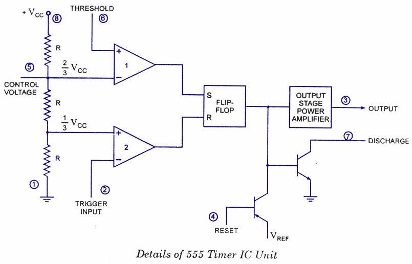
555 timer ic internal diagram structure comparator trigger two flip flop schmitt voltage inside components look figure positive example circuits555 cmos lm555 invention repeating circuitstoday Astable multivibrator using 555 timer555 circuit timer ne555 ne555p operating basics precision clock fig ichibot.

Timer graham lambert
Ic 555 pinouts, astable, monostable, bistable modes explored555 timer ic: introduction, basics & working with different operating modes 555 timer icTimer matlab.
.


555 Timer IC: Internal Structure, Working, Pin Diagram and Description

IC 555 Pinouts, Astable, Monostable, Bistable Modes Explored

Introduction to the 555 Timer - Circuit Basics

Astable Multivibrator using 555 Timer

IC 555 Pinouts and Working Explained

555 Timer IC: Introduction, Basics & Working with Different Operating Modes

555 timer IC - Wikipedia
Ready to help: Functional Block Diagram of IC 555